|
|
|
|
|
|
|
|
|
|
 | FAQs |
|
|
|
|
FAQ Nixietubes – nixieclocks
If there is anything you would like to discuss, please use our forum.
If you are looking for nixie tube data sheets see here.
General information about multiplexing:
Here's an explanation specific to using nixies - though it's
applicable to any similar situation, with changes to the details :)
Multiplexing is the technique of using one wire to do the work of many
- in our case, we might use ten wires to do the work of sixty - at the expense of a little more complication.
Consider a single nixie tube. High voltage, anode resistor to limit the current, and ten cathode wires, one of which must be connected to ground to illuminate a single digit. If you're driving this, using a direct drive you'd (usually) arrange to have the cathodes controlled using either a driver chip of some flavour (e.g. the 74141/K155) or with discrete transistors. The anode you leave connected through the resistor.
Which is fine. Drive the cathode you want and the digit lights up. It takes ten wires to control things.
But if you want two tubes, driving them the same way, you need twenty wires, four tubes forty wires, and so on. You also need as many drivers as wires... Even if you're using the K155 chip, you need one per tube, or you need a heap of transistors. Your circuit board has also become more complex and probably bigger, just to fit the bits on.
So what can we do to reduce this complexity, cost, and size?
If we fasten all the cathodes in parallel, we suddenly find we only need ten transistors (or one K155) but there's some bad news - we have to show the same digit on each display... and a clock which can only display 11:11 or 22:22 is probably of limited usefulness.
However, if we arrange somehow to switch the anode connections, we can make things happen differently: for example, if the time is 10.35, we would first switch the anode power to the hours/tens digit and drive it with a '1'. After a short pause, we do the same with the hours/units digit and send a '0'. The same for the minutes, sending a'3' and '5'.
If we do this at the right rate, persistence of vision persuades the eye that all the nixies are lit at the same time, and we've replaced forty transistors with about 14 (depending how you've switched the anode voltage); we've reduced the number of output wires from the processor - you don't really want to do this with a non-processor design, since that would generally already have the data in a non-multiplexed form which you'ld have to multiplex before you displayed it - and we've reduced the circuit board component count and real estate and cost.
Hope this helped a bit.
1. How do I power a nixie tube?
(A) With current-limited high voltage 120 to 250 volts DC depending on tube type. 180 volts is a typical value which works with most common types.
2. How can I generate the high voltage required for driving nixie tubes?
(A) With current-limited and rectified mains [if you have 230 volt mains or similar]. (B)With high-voltage transformers such as those which were installed in equipment which originally used nixie tubes. You did save the transformer, nixie sockets, driver ICs and HV transistors when you took the tubes out of that old piece of gear, didn't you? (C) With "back-to-back" transformers. [see next question] (D) With a custom step-up switch mode power supply. (E) With a capacitor-diode multiplier.
3. What's this about "back-to-back" transformers?
(A) You can get nixie drive voltage using a pair of low-voltage transformers in series, with their secondaries connected together; the second [output] transformer will then be powered in the reverse of the way it would usually go. If you use transformers with the same output voltages [turns ratios], this forms a slightly inefficient isolation transfomer but only puts out approximately the same voltage as the mains input. However, if the output transformer has a lower secondary voltage rating, dual primary windings, or higher primary voltage rating, the output voltage of the pair can be higher than the input voltage. This is useful for those living in "low voltage land" [North America and Japan].
4. How do I current-limit the power to a nixie tube?
(A) Using a resistor in series with each tube's anode supply connection. The value sets the current. Normal values for direct drive are 33k to 82k, normal values for multiplexed drive are 4k7 [= 4.7k] to 27k. Calculate the value needed by R=E/I, where I is the desired current in milliamperes, E is the difference between your supply voltage and the tube's maintaining voltage, and R is the needed resistor value in kilo-ohms. With direct drive displays [see below], do not attempt to take the shortcut of using a single resistor for multiple nixies!
5. How can I control the high voltage signals needed to operate a nixie tube?
(A) Using high voltage transistors, optocouplers and/or vintage 7441, 74141 or similar IC drivers. (B) Using recently-made special high voltage driver ICs made by Supertex, Dionics, or others.
6. Where can I find data for nixie tube type "XXXX"?
(A) We have in our Links section available via the navbar on the left side of most pages, links to several sites which feature significant amounts of nixie tube data [Links > Tube Data Resources]. An index is available which tells what data are at each site. (B) There are probably data for other types available online. Try a web search with your choice of search engine, using a few variations of the type number [with and without hyphens, spaces, slashes, etc.] and brand name.
7. What does multiplex / direct drive mean? What are "muxing" and "time sharing"?
(A) Direct drive: all tubes have a constant supply and light at the same time. (B) Multiplex: only one tube [or a few out of many tubes] driven at a time. The updating/switching speed is so fast that all appear to be lit at all times. Multiplex is often shortened to "mux" [muxing, muxed], and sometimes called "time sharing" in vintage documents.
8. Why use direct drive?
(A) Can be made with standard logic parts, easy to understand, does not need a microcontroller or programming skills. (B) No high peak currents, no high voltage / high frequency switching noise. (C) Gives brightest display.
9. Why use multiplexing?
(A) Reduced component and signal conductor counts. (B) Compact and simple electronics; easier, faster and cheaper to assemble. (C) Dimmer display compared to direct drive, sometimes a desirable feature.
10. How can I generate a one Hz signal for my clock?
(A) Mains power at 50 or 60 Hz frequency is adjusted for good short-term and excellent long-term accuracy in most industrialized countries. Just divide it by 50 or 60 to get 1 Hz. (B) For portable / battery-powered clocks crystal control is the simplest way, but good accuracy is always a challenge. (C) See the next question.
11. Is there a way to keep a clock synchronized to a master time signal?
(A) GPS [worldwide; a.k.a. NAVSTAR], WWVB [continental U.S.A], DCF 77 [Germany/Europe], HBG [Switzerland], MSF [U.K.], RJH [Russia], JJY [Japan] and other radio transmissions are available for extremely accurate government-maintained timekeeping signals. Most or all commercial receivers of these signals also make available an accurate 1 Hz pulse.
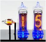
12. My nixie doesn't glow pure orange, it's more pinkish, with a blue/purple haze. What's wrong?
(A) Probably nothing! The most advanced nixies, often called "Ultra Long Life" types, use quite a bit of mercury to prolong their life to 100K hours or more - this equals *decades* of continuous operation. In some tubes, this produces the strange coloration described at normal operating current. In other tubes, the effect is only objectionable at higher than normal currents [as might be used in a multiplexed display]. In original use, these tubes typically either had an orange/amber/red filter coating, or were placed behind a similarly tinted window or lens to block the blue color and greatly improve readability.
13. How can I remove cracked, damaged, or undesired orange/red colored filter coating?
(A) Just place the tube in hot tap water for several seconds to a few minutes, and you can easily rub it off. Unfortunately, tube markings stamped on top of the coating will also be lost, so you may want to re-label with at least the type number in case you [or your heirs] need to replace tubes after a few decades.
Other questions from E-Mails
I have all the components soldered on the boards. I now want to start connecting the tube sockets. I am using National 900 tubes, and don't know which pins are for what.
You need to test that by using a 47k resistor in series with the hi voltage supply, that is your anode supply and then a wire from ground from the powersupply, then you find the anode of
the tube by looking into the glass when that is found you try to connect it to the resistor with hi voltage on it. Then test all digits with the ground wire, and write it all down. if you can light up all 10 numbers the tube works, if not if is maybe defective or you have not connected the anode supply to the right anode pin.
Also I don't really understand the schematic. It looks like each wire connects to 3 tubes (I am building the 6 tubeclock). How can this work? Won't all 3 tubes display the same digit? I'm sure I'm missing something, but it seems like each tube should have its own wires.
Please see on the schematic that those 3 tubes has seperate anodes and they are connected to 3 different anode drivers. So imagine only one of them is lit at a time, then it will work fine if all numbers are connected together. That is called multiplexing. the same thing happens in the other 3 tubes, so 2 numbers is lit at a time, and then switched through all 3 tubes.
this clock uses 2 x 3 muxing to display 6 numbers, like hr, min and sec.
> The component that goes in the X1 spot is different than the one shown in
the diagram. Does it matter which way it goes in the board?
Not at all.
> I put it in with the writing facing the outside of the board. Is that ok?
The components are placed into the boards at that side with the text, some components will maybe cover some text, but that is fine. Please have a look at the webpages with the nice closeup pictures, they will make it much more easy for you to make it right.
> On the 4-wire connection between the boards, do the wires run straight across, or cross over (square hole to square hole)?
Square hole is pin 1 on both boards. pin 1 is connected to pin 1 and 2 to 2 and so on..
so you are right, square hole to square hole.
Heating of Q7
Q7 will get hot, that is normal, depending on your input voltage that is within what range ??
9V AC loaded is the best voltage.
Depending on your anode resistors and tubes the power usage will also change, but we have measured Q7 to be from 40 to max 55 C hot, without any additionaly cooling, 55 C is not at all critical, but it feels burning hot with your fingers, ((warning hi-voltage, test just after poweroff !!)) but remember those power fets are designed to handle 80 - 100 C without problems.
You can mount Q7 on an isolated heatsink, or your case using isolators as usual, it will longen the lifetime, to get it from 55 C to 22 C (room temp), but remember to keep the 3 wires as SHORT as possible, else you might add oscilations and switch frequency over tones that might add more heat, or even make EMI that will make your AM/FM radio or even TV go crazy.
Test this with a pocket AM radio to see if any changes before / after.
Q. : Hi Thomas, > i think an other way to solve the heat issue is to install a mosfet which has higher specs so it does not get as hot as the irf730 can you tell me if the irf730 can be replaced by eg the IRF740, IRF840 or other item. I checked the voltage regulator but that one is not getting hot this might be the easiest way thanks
A. You can try, but it is not only the internal resistance that makes it hot, it is also the switching loss, due to weak gate driver, changing to a lower internal resistange also adds gate charge, and then adding more switch loss, the 730 type is choosen to give best trade-off of both things that will add heat. Also the FET is NOT cooled, so 500mW will boil it.
Best and cheepest solution is to add a heatsink, but also remember not to add too much capacitance to the drain. Remember switching 200V at this speed WILL generate switching loss.
If you can accept lower light output, why not trying to lower the Anode voltage to 170V or even 160V, also try changing the anoderesistors, also if you chenge the FET you need to change the hi-freq noise reduction the cap and resisror, you need a super hispeed scope and hi voltage probe, it is not as easy as many thinks. it is right now best for the price used.
High Voltage problems
Hi Thomas and Claus,
Once again, I appreacite all of your help here...
So, I closely reexamined the board, and you were right, I had the transistors in Q8 and Q3 reversed. After a quick trip to the electronics store I resoldered those pieces in place. The board still seems to be not working??? When I measure between TP1 and Earth (ground) I get 12.56-12.59 v-dc? Something still seems like it isn't working - Any ideas?
Jamie.
Yes,
Jamie, the hi-voltage is not working. If it has not been working at all:
Q7 mounted the wrong way ?
D5 is shorted ?
IC5 NE555 is mounted the wrong way ? or maybe bad connection to one pin ?
Q8 is PNP instead of NPN ? it must be a MPSA42
R23 or R7 or R24 values ? or solderings ?
also if R26 - R27 - C14 is wrong value it will not work.
Since you have about 12V DC on TP1 the value goes directly through D5
You did not say the input voltage at C3, so I cannot guess if D5 is working or shorted.
if it has been working but is now defective,something, component must be burned, look for hot black smelling parts :-)
As always:
if your skill and bad luck is troubling you,it is possible for you to send the compleete clock to my address in Denmark and also pay for return postage, and pay the dead components plus a small check and repair fee 20 Euro.
1 PPS INPUT
Q. I'm not sure which one of you might be able to answer my question, so I've copied both of you...
I've been running my Nixie Clock (Ver 1.08; software shows "58" at power on) for about 6 months.
I've recently tried to use a 1 PPS GPS signal to synchronize the clock to a better timebase than the internal crystal, but have not yet had any success.
I'm applying the 1 PPS pulse to the "GND" and "DCF" input pins on J1 of the PCB. It appears I have to use an inverted 5 volt input (high for 0.9 seconds, then low for 0.1 second) to get the green LED to pulse properly, as indicated in the documentation.
I have the green LED pulsing now, but the clock still seems to be gaining about 6 seconds per day - just what it was doing with no external input signal.
Is there something else I need to do to sync to my 1 PPS input signal, or something else I can check??? I haven't yet confirmed that the GPS signal is exactly 86400 pulses per day, but I'm in the process of modifying another clock to do just that...
A. The 1PPS needs to be input at the 50/60/1 Hz input pin. The DCF77 input is ONLY !! for DCF77
That is why it does not work for you.
Inputting 1pps into the DCF77 signal will fool it into DCF mode, but it cannot find correct time, and screen goes black. It is not clear in the doc how to input the 3 different clock sources.
http://www.nixieclocks.de/english/downloads/docuenglishv108.pdf
But in the schematic you will see what I mean:
http://www.nixieclocks.de/english/downloads/108b6.pdf
WWVB
Since we both live in Europe, Germany and Denmark the real WWVB signal is impossible for us to recieve, and therefore also impossible to test and develop a good decoder for, you can imagine all the problems selling a decoder routine that does not work prfect, so it is better not to have one = no problems.
if only I could get access to a signal simulator, maybe a PC program that can generate the digital pulses, and add realistic noise problems, but this is so far impossible to find and belive me, we have tried and asked a lot of US freaks to find/make one, but no such luck.
All the programs and samples and so on we have got and have testet did not work, and was useless in the matter of making a WWVB decoder routine.
DIODES
Q. : A while ago, I purchased a tub board from you (v. 1.06), and cannot >get a correct diode for this board. What are the cross diodes for D5, the BYV 95C. The NTE 569 is too big. Glenn
A. Any fast switching Hi voltage diode will work. as in any case when you can not get to right device, in this case BYV95C, always look up the right device datasheet.
http://www.alldatasheet.com/datasheet-pdf/pdf/61974/GE/BYV95C.html then see what the local shop have that macthes the voltage and current and speed.
The byv95c is a 600v and 250nS fast, with only 10pF junction. a byv26c will be an ok one, even if it has a much higher capacitance, but I guess you can try to use an 1N4005 or 1N4006 or 1N4007 but double check the temperature on the FET and Diode. More loss will give you hotter components.
If you happensto have a NTE569 on stock, I would mount it standing, and be happy.
About multiplexing:
1.Muxed clocks, will always have lower brightness, but if it is still bright enought why worry.
2.Since the tubes are switched on and off fast, several hundrede times a sec, some tubes can "sing" make an audioble sound, dont place the clock near your bed side.
3. Muxed clocks need less parts, making them less expensive and faster to make, lower chance for defects, lower chance for errors.
4. We have many people using our boards with IN18, they are all happy.
5. Direct driven clocks will always lit up more, and wear down the tubes faster and use more power from the mains, you pay this right ..But they can run 100% slilent !
6. If a direct driven clock have brightness adjustment, it is done using time on/off switching, you can not lower the voltage or change anode resistor value to adjust the brightness of a Neon tube.
7. Several Direct driven clocks have this, to longer the life time, and turn down the brightness, else you have to wear sunglasses.
8. So why not go for a muxed design ?
Also our clock with 6 tubes are made using a 2 by 3 muxing system, that lit up two tubes at a time, then the next two, then the last two, and repeat. So we get the most good out of everything.
Our clock can handle many tubes, dual anode types, 7971 types, normal nixies, from 2 to 4 to 6 tubes, and even radio controlled, if you are located in Europe ?
think about it.
Lifeftime Calculation
I would like to know, how long can I expect tubes in a clock built with your kit to last? I will be running it full time in my office. That is 24/7. I think the Klok K-7 is spectacular, but if I need to replace the tube every 2000 hours that is less then once a year!! Since a set of tubes run $175, the cost of the initial clock is not as important as the maintenance cost of replacing tubes. The actual sound (if there is one) would probably be low.
Unless the tubes are *very* dim brightness should not be an issue. I am ready to buy this kit. I have a EE degree, and know my way around a hot iron, it does not matter to me how complex whatever kit I buy is. I am jut worried about replacing hard-to-find tubes in the future, and don't want to have to buy spares at this time. It would be cheaper to buy a direct drive if there was *that* much of a difference in tube life. I have seen claims of 10 years for direct drive units, so you understand my wanting to see what the difference in life is. Thanks again for your indulging my curiosity.
Calculating lifetime is difficult.
You are right the initial datasheet with 2000hr is crasy low, I dont know how this value was calculated, maybe something with when the brightness drop a certan level ? at same current ?
or emmision materials have darkened the glass to a measureable level ?
no matter what, when they are lit, something will wear, more bright = more wear.
our muxed clock have several brightness levels, you can either change this manually, or add and LDR so it will be done automaticly, our lowest level is about 1/20 dutycycle in this mode your 2000 hr will be 2000 x 20 = 40000 hr
Our muxed lit/off periodes for each tube is like this:
4 - 600uS/2500uS = 0.24 or 2000hr x 4 = 8000hr
3 - 265uS/1700uS = 0.16 or 2000hr x 6 = 12000hr
2 - 165uS/1800uS = 0.09 or 2000hr x 11 = 22000hr
1 - 119uS/2400uS = 0.05 or 2000hr x 20 = 40000hr
You see at level 4, the 600uS on periode for two tubes, then the next and next = 1800uS on time in a 2500uS time frame, all DCF and other parallel software stuff takes a bit time, the most perfect number would have been 833uS on.
but I needed to sync up the muxing and handle perfect timings, no matter what, we want to have a constant light level !!
The program inside the microcontroller is made using C, with 10 included files of total 56kb of source code compiled down to 7kb executable code.
I still think the IN18 rating off 2000hr is crasy low numbered it is impossible to wear a tube this fast by normal usage, maybe they have rated the current 10 times higher to compeete into the hi brightness world ?
I have all my nixie clocks running 24/7 both home and at work, att it the highest bright level, all my tubes still looks like new.
Strange signs in tubes (ghosting etc. )
If you are having problem with extra signs on tubes, ghosthing or other strange looking readouts.
The most normal problem is a anode driver problem.
We have several approches for this one -
always first try to swap the two 74141 easy they are in sockets.
If then same problem, look for short circuits at the tubes, we have even seen some tubes with internal short.
if nothing there, look at the anodedrivers.
Power off, take out PIC16, add power, take a wire from pin 20 (+5V) and connect to pin 24-25-26 one at a time, then measure J1 pin 1-2-3 to reveal any anodedriver problems.
Defect transistors MUST be replaced with similar types !
Also there are two different types, NPN and PNP, if swapped the system will not work, also the resistance values must be right.
Ghosting: weak strange numbers or many numbers weakly lit always in all tubes. this often happens if the drive voltage it too hi, adjust the voltage down and see the result, 180V can on some tubes be too much, try 170V.
|
|
Important
Datasheets
|
|
|
|
|
|
|
|